


A chemical pump minimum flow bypass is a recirculation path that keeps a centrifugal pump moving enough liquid when the process line is throttled, blocked, on standby, or temporarily below the pump maker’s minimum continuous flow. In corrosive service, the bypass is not just a small convenience line. It has to protect the pump from heat, vibration, seal stress, and deadheading while also sending aggressive liquid to a place where temperature rise, fumes, splash, and tank level changes are controlled.
The mistake we see in many early layouts is simple: the buyer sizes the pump for the production flow, then the skid builder adds a control valve, filter, spray header, or intermittent filling step that can drive the actual flow close to zero. The pump still rotates. The motor still sounds alive. The discharge pressure may even look stable. Inside the casing, however, the liquid may be heating, flashing locally, or pushing hydraulic loads into the impeller and shaft. That is where the bypass decision belongs, before the pipe is cut.
The field risk a bypass is meant to remove
A missing bypass usually shows itself indirectly. Operators report that a pump is noisy only when a downstream valve is nearly closed. Maintenance sees a seal leak after short standby periods. A filter loop runs normally in production, but the pump housing feels hotter during rinse, batch hold, or line changeover. These are not always pump-quality problems. They can be duty-point problems.
For a centrifugal chemical pump, low flow can mean poor internal cooling, unstable hydraulic loading, and high recirculation inside the casing. The U.S. Department of Energy notes in its guide to centrifugal pump flow control that throttling and control method choices affect pump energy and operating behavior. The same operating-point thinking matters for reliability. If the system asks a pump to run far away from its intended curve region, the pump may survive for a while, but the weak point often appears as heat, vibration, bearing load, or leakage.
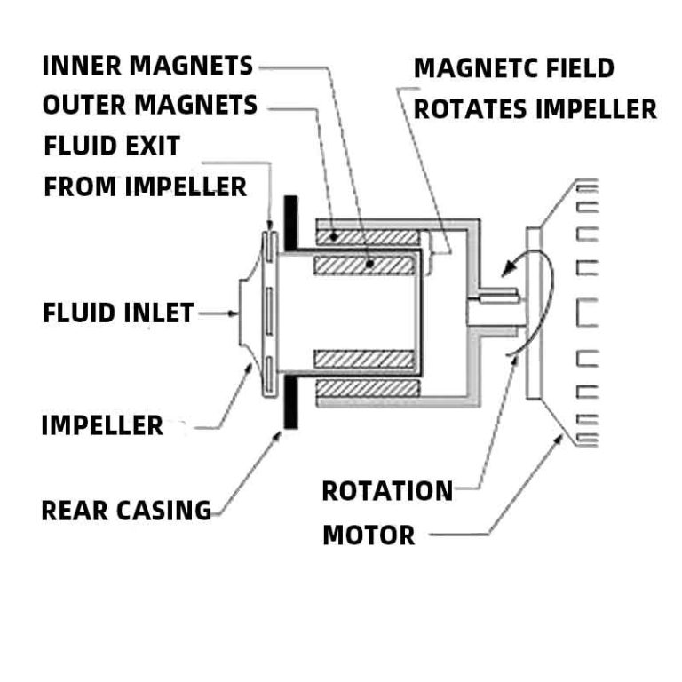
In chemical service, those symptoms deserve more caution than in clean water. A hot casing may change vapor pressure margin. A small shaft-seal leak may expose staff to acid, alkali, oxidizer, or solvent vapor. A magnetic-drive pump removes a dynamic shaft seal, but it still needs liquid movement for heat removal around the containment shell and bearing surfaces. A bypass does not make any pump immune to poor application; it gives the system a controlled escape route when the process demand drops.
This is also why a bypass is different from a pressure relief valve. A relief valve protects against excessive pressure under a defined condition. A minimum flow bypass protects the pump against insufficient flow. On some packages both may exist, but they answer different failure paths. If the specification only says “add safety valve” without minimum-flow logic, the designer may miss the real low-flow risk.
Minimum flow is a pump limit, not a valve preference
Minimum flow should come from the pump selection, impeller trim, liquid condition, speed, and manufacturer guidance. It should not be guessed from pipe diameter. Crane Engineering’s overview of minimum flow bypass lines describes the bypass as a way to keep a pump above its required minimum when process demand is too low. That practical idea is useful, but the number still has to be tied to the selected pump, not copied from a previous skid.
For a buyer, the safest wording is not “provide a 1/2 inch bypass.” Better wording is: specify the pump model, duty point, liquid, temperature, specific gravity, viscosity, and expected lowest process flow; then ask the supplier to confirm the minimum continuous stable flow and the bypass arrangement. The orifice, valve, return point, and interlock should follow that answer.
There are several ways to provide bypass flow. A small continuous bypass with a restriction orifice is simple and hard to forget. It also wastes energy and may overheat a small tank if the line runs all day. A manual bypass valve gives commissioning flexibility, but it depends on operator discipline. An automatic recirculation valve or control-valve loop can open when process flow falls, but it costs more and needs maintenance. In chemical duty, the choice also depends on whether the bypass liquid can safely return to the tank, suction chamber, or a neutralization/collection area.
| Bypass approach | Where it fits | Watch point in corrosive service |
|---|---|---|
| Continuous restriction orifice | Simple transfer loops, small pumps, predictable standby flow | Confirm heat rise in the receiving tank and avoid sending hot corrosive liquid near operators. |
| Manual bypass valve | Commissioning, temporary operation, systems with trained operators | Needs lockable position or clear procedure. A closed manual bypass is the same as no bypass. |
| Automatic recirculation valve | Unattended packages, variable process demand, frequent low-flow periods | Confirm wetted materials, pressure drop, minimum opening behavior, and maintainability. |
| Flowmeter plus control valve | PLC-controlled chemical loops, batch equipment, higher-value process lines | Sensor placement and calibration matter. A drifting meter can hide real low-flow operation. |
Minimum flow also interacts with the pump curve. If the selected pump is already far to the left of its best efficiency region at normal duty, a bypass may hide the symptom but not fix the selection. QEEHUA’s article on pump curve versus system curve checks for PCB chemical pumps is a useful companion when the design has throttled operation, changing filter pressure, or multiple branches.
Routing a corrosive recirculation line without creating a second problem
The first routing question is where the bypass returns. Returning to the supply tank is often safer because it gives the liquid volume more time to absorb heat and lets the pump keep a clear suction source. Returning directly to the suction pipe can be compact, but it may recycle heated liquid into the pump inlet and reduce NPSH margin. In volatile, hot, or high-specific-gravity liquids, that shortcut deserves a hard review.
A long bypass line is not automatically bad. It may be the right choice if it returns the liquid below the tank surface, away from personnel, and away from a pH probe or level switch that would be disturbed by turbulence. A short bypass line is not automatically good. If it dumps near the pump suction nozzle, it can create swirl, air entrainment, or a misleadingly warm suction condition. In acid or alkali service, the return point should also avoid splashing, mist, and localized attack on tank internals.
The bypass should not defeat the process. On a filtration loop, sending bypass flow around a filter may keep the pump alive but leave the bath under-filtered. On a spray line, a bypass may drop nozzle pressure below the cleaning or etching requirement. On a transfer line, a bypass may make the operator think the pump is moving liquid to the destination while most flow is quietly returning to the source. The control philosophy should state what happens during bypass operation, not only show a pipe on the P&ID.
QEEHUA’s earlier article on magnetic-drive pump deadheading covers the no-flow failure side. A minimum-flow bypass is the design response when the process cannot guarantee enough flow at all times. The two topics are close, but they are not the same user intent. Deadheading asks what happens when the pump is blocked. Minimum-flow bypass asks how to design a recirculation path before that blocked or throttled state damages the pump.
A practical field check is to stand at the planned skid and follow the liquid path with one finger on the drawing. If the discharge valve closes, where does the flow go? If the return tank level is low, is the bypass outlet still submerged? If the operator isolates a filter, does the pump still see enough flow? If the bypass valve clogs with crystals or debris, which instrument tells the PLC or maintenance team? These questions are plain, but they catch many expensive errors.
Controls, valves, and checks that make the bypass useful
A bypass line is only useful when it opens, passes the required flow, and does not let liquid move the wrong way. For continuous orifice bypasses, confirm the pressure differential across the orifice at the lowest and highest expected operating points. For controlled bypasses, confirm the flow signal is taken from a location that represents real process flow, not recirculated flow. QEEHUA’s discussion of chemical pump flowmeter placement is relevant here because a meter installed in the wrong leg can make the control system confident and wrong at the same time.
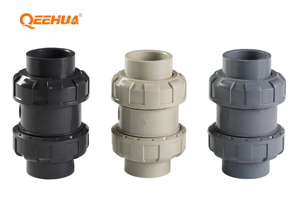
Check valves are often overlooked. If the bypass returns to a tank or shared header, backflow can occur during shutdown, tank level changes, or another pump’s operation. A check valve in corrosive service needs material compatibility, enough cracking pressure margin, and a position that can be inspected. Do not place it where a stuck disc becomes invisible until the pump fails.
Temperature is another useful signal. A pump casing, containment shell, or bypass return line that gets hotter during low-flow operation tells you the recirculation path is not removing heat fast enough. This does not mean every small pump needs a temperature transmitter. It means unattended corrosive systems should have some way to detect the low-flow state that matters: flow switch, pressure trend, motor load, temperature, tank level, or a PLC condition that stops the pump before damage becomes leakage.
The bypass valve material should be selected with the same seriousness as the pump wet end. Polypropylene, PVDF, ETFE-lined parts, ceramic, carbon, elastomer, and metallic hardware each have limits. Concentration, temperature, oxidizing strength, solids, and cleaning chemicals all matter. Do not accept a bypass bill of material that says only “plastic valve” on a chemical package.
Commissioning should prove the bypass, not just photograph it. Start the pump at a normal duty point, then simulate the low-flow condition in a controlled way. Confirm that the bypass opens or passes the expected flow, the pump noise does not change sharply, the casing temperature stays reasonable for the liquid, and the return line sends liquid to the intended place. Record valve positions and instrument readings while the system is healthy. Those numbers become the maintenance team’s baseline when someone later reports vibration, heat, or unstable discharge pressure.
For automatic systems, test the failure state as well. Unplug or isolate the flow signal according to the control procedure, verify the alarm response, and confirm the pump stops or moves to a safe state before the chemical line is left unattended. A bypass that depends on a single hidden manual valve should be tagged clearly. If operators rotate shifts, the drawing, valve tag, and field label need to tell the same story.
What to send the pump supplier before the drawing is frozen
A supplier can give a better answer when the low-flow case is visible. Send the normal duty flow and head, the minimum process flow, the maximum discharge pressure, the liquid name and concentration, temperature range, specific gravity, viscosity if above water-like conditions, solids or crystals, tank level range, suction pipe layout, and whether the pump may run against a closed valve during batch steps. Include whether the bypass returns to the source tank, suction line, or another vessel.
For corrosive lines, also send the operating rhythm. A pump that runs continuously at low bypass flow has a different heat problem from a pump that sees a closed valve for ten seconds during valve switching. Batch frequency, standby time, and operator access change the control answer. If the skid is exported or installed in an unmanned area, the bypass should be less dependent on memory and more dependent on hardware or interlock logic.
Procurement note: write the minimum-flow requirement into the RFQ, not only into a later P&ID comment. Ask the supplier to confirm the required bypass flow, suggested bypass method, wetted materials, and any low-flow operating limits. If the line also has a filter, heater, spray nozzle, or flowmeter, send the full loop instead of only the pump tag.
For head and pipe-loss questions that affect bypass sizing, the related QEEHUA article on total dynamic head in chemical pump systems can help the buyer separate pump head from the rest of the piping loss. That distinction prevents a common error: blaming the pump when a bypass, filter, elbow, or undersized return line changed the operating point.
The final design should be boring in operation. The pump sees enough flow. The tank does not overheat. The bypass return does not splash. The valve material matches the liquid. The operator can tell when the system is in bypass. Maintenance can inspect the check valve and orifice. That is a much better outcome than a pump that looks fine on the purchase order and fails quietly during the first month of intermittent operation.
If you are reviewing a corrosive pump skid with intermittent flow, send the liquid, duty point, tank layout, and low-flow scenario to info@qeehua.com for a practical pump and bypass discussion.
FAQ
Should a chemical pump bypass return to the suction line or the tank?
Returning to the tank is often safer because it gives heat and turbulence more volume to dissipate. Returning to the suction line may be possible on compact systems, but it must be checked for temperature rise, NPSH margin, air entrainment, and chemical safety.
Can a relief valve replace a minimum flow bypass?
Usually no. A relief valve responds to pressure, while a minimum flow bypass ensures the pump has enough liquid movement. Some systems need both protections because overpressure and low-flow damage are different failure modes.
Does a magnetic-drive pump still need minimum flow protection?
Yes, when the selected pump and duty require it. A magnetic-drive pump has no dynamic shaft seal, but internal bearings and the containment shell still depend on suitable liquid circulation and temperature control.
What information is needed to size a chemical pump bypass?
Provide the pump model or curve, normal and minimum process flow, head, pressure, liquid chemistry, temperature, specific gravity, viscosity, tank layout, return location, and operating rhythm. The bypass should be based on the selected pump’s minimum continuous flow.
Why does a pump get hot even when the motor is running normally?
A motor can run normally while the pump is moving too little liquid. At very low flow, energy can become heat inside the casing, and internal recirculation can increase vibration, noise, and component stress.
A bypass check that uses numbers, not habit
The first number to ask for is the pump’s minimum continuous flow. Do not guess it from motor size. Minimum flow can be tied to internal recirculation, heat rise, vibration, bearing load, or seal condition. A safe bypass flow must keep the pump above that limit when the process valve closes or when demand falls below the pump’s stable range.
A simple RFQ check is: required bypass flow = pump minimum continuous flow minus confirmed process flow at the low-load case. This should be reviewed with the pump-control cautions in the U.S. DOE centrifugal pump control guide. If the process can fall to zero, the bypass must cover the minimum-flow requirement by itself. If the process still consumes some flow, the bypass can be smaller. The return point also matters. Sending hot or aerated liquid back to a small suction tank can create a different problem, especially with corrosive or volatile liquids.
The U.S. DOE pumping-system material treats bypass flow as useful for protection but poor as a normal flow-control method. That is the tradeoff. A bypass can save a pump during low demand, but a continuously open bypass can waste energy and increase tank temperature. For chemical service, it can also add unnecessary circulation through fittings, valves, and seals. The better design is to decide whether the bypass is continuous, restricted by an orifice, controlled by a valve, or replaced by another control method.
